The base TS-960 platform uses the advanced GX5296 – a 3U PXI, 32 channel 125 MHz digital I/O card featuring timing and PMU per pin capability with sub-nanosecond edge placement resolution. A wide range of digital and analog instrument test options can easily be incorporated into the TS-960, offering users a compact test system that can support both functional and DC parametric test capabilities. And with the incorporation of an integral, modular test interface, the TS-960 offers users an application ready test system which can be upgraded or reconfigured in the field if needed. The system is also supplied with various software development and digital vector conversion tools, including support for ASCII, WGL, STIL, VCD/eVCD and ATP vector formats.
TS-960 Core System Configuration
The basic TS-960 core system includes the following test resources and capabilities:
20-slot, high-power PXI chassis with integral receiver interface
Embedded Core 2 Duo controller with Windows 7
64 125 MHz digital channels with per pin PMU and per pin timing (expandable to 512)
64 static digital channels (expandable to 128), which can be used for fixture ID, UUT static control or DUT board relay control
Programmable 0 to 48 V DPS (expandable to multiple channels)
System self-test fixture and test program
ATEasy test executive and programming environment
Advanced digital waveform editing and display tool
ICEasy test software development tools
Receiver Interface
The TS-960 platform employs a modular, pogo-pin style receiver interface which consists of various pin blocks and is field re-configurable. Interfacing to the device under test (DUT) is done via a device specific PCB which mates to the pogo pin interface and is held in position with an integral stiffener / hold-down assembly. The hold down assembly employs a slide receiver mechanism which facilitates interfacing to handlers.
For digital interfacing, the receiver employs dual, 68-pin block assemblies which connect directly to the TS-960’s PXI digital instrument resources, providing a high performance, controlled impedance interface. For user power connections, a power block is available which supports up to (4) user power suppliers and for general purpose analog and switching applications, a 78 pin block assembly with mating D-sub connector is available. RF and coaxial connections can be accommodated via an 8 connector, SMA block or blind-mate RF connector blocks. All receiver block positions are interchangeable, offering a high degree of flexibility.
TS-960 Receiver Interface
System Self-Test
The TS-960 is supplied with a system self test which includes an interactive self-test software procedure as well as a self-test PCB which interfaces to the receiver. The self-test is an ATEasy based test program and verifies functional integrity of the system and resource connections to the test system interface.
TS-960 Self Test Fixture
Software
The TS-960 is supplied with ATEasy, Marvin Test Solutions’ test development and test executive software suite; digital waveform tools for developing, debugging and importing digital test vectors; ICEasy – a library of device test development tools; and all necessary instrument drivers which are compatible with variety of application development environments including ATEasy, LabWindows, LabVIEW, Microsoft Visual Studio languages and more.
The TS-960 ATEasy work space is provided with a pre-configured ATEasy System file and associated instrument drivers.
It also provides access to DIOEasy and ICEasy tools, which provide the following capabilities:
Pin and pin group mapping
Virtual instrument drivers – providing digital subsystem and instrument independent test programs
IV Curve plotting tool
Shmoo plot tool
Pre-defined parametric and functional tests
Self test source code
Predefined test examples
Import tools supporting WGL, STIL, VCD and EVCD file formats using the optional DIOEasy-FIT option
Automated DC Parametric Test Creation
ICEasy’s library includes a full set of test capabilities for characterizing a device’s input and output DC characteristics. Utilizing the TS-960’s PMU per pin capabilities, users are able to quickly create test programs for the following types of tests:
Open and Shorts
Input Leakage (IIL, IIH)
Input Voltage Threshold (VIH, VIL)
Output Short Circuit (IOSH, IOSL)
Output Voltage Threshold (VOH, VOL)
Power Consumption (IDD, IDDQ)
These preconfigured tests, when combined ICEasy’s Device Pin and Pin group mapping capability provides the user with a simple and streamlined method to assign tests to specific device pins as well as specifying pass / fail limits for each test, without having to do low-level instrument setup and control. The result is faster test creation and faster time to test.
I-V Curve Tool
ICEasy’s Current – Voltage (I-V) curve tool offers users the ability to graphically plot the I-V characteristics of a device’s ESD diodes. This test method can provide insight into device failure mechanisms that can affect a device’s I/O pins, such as electrical overstress (EOS), electrostatic discharge (ESD), bond wire problems, and packaging problems. And more recently, the use of I-V curve plots as an “impedance signature” may be useful in identifying counterfeit devices where the impedance or I-V signature of a known genuine part is compared to a suspect part.
ICEasy’s I-V curve tools allows users to easily setup voltage & current ranges and step increments as well as defining by name, the specific pin (or pins) to be tested. Additionally, all I/O pins can be plotted on the same graph, providing an easy way to compare all device I-V curves. (see figure below) The plotted data can also be easily exported via the TS-960’s test executive (ATEasy). The ability to easily measure I-V characteristics and plot the results is a key feature for failure analysis and design verification applications.
IV Curve Tracer Tool
Shmoo Plot Tool
ICEasy’s Shmoo plot tool allows users to easily vary test parameters on both the X and Y axis without programming – allowing test engineers to visually observe the pass / fail operating ranges of the device under test. An accepted test methodology for device characterization and qualification, the addition of the Shmoo plot feature to the TS-960 platform provides users with a powerful technique for design verification and early production test qualification. Supporting both automated and interactive control, ICEasy’s Shmoo tool allows users to change parameters on the fly or to control the test via the TS-960’s test manager (ATEasy) as well as logging the resulting data.
Shmoo Plot Tool
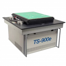
Configuration Option
TS-960 with Manipulator
Applications
Design verification for devices and modules
Pilot production and focused production test
Automated failure analysis and test
Counterfeit device detection
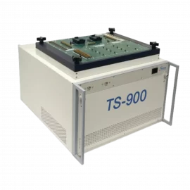
Description
The GENASYS Semi TS-960 PXI Semiconductor Test System is an integrated test platform that offers comparable system features and capabilities found in proprietary ATE systems. Available as a bench top system or with an integrated manipulator, the TS-960 takes full advantage of the PXI architecture to achieve a cost-effective and full-featured test solution for device, SoC and SiP test applications. The test system incorporates a high power (60 watts per slot) PXI chassis and a custom-designed, performance test interface that supports the use of PCB DUT (Device Under Test) boards – a proven and high-performance method for interfacing to the device under test. Additionally, the receiver interface’s pin blocks are field configurable, allowing users to upgrade the receiver when they modify or upgrade the system for new applications. The configuration of the receiver can support up to 512 dynamic digital channels, as well as a range of analog, device power supply (DPS) and RF resources.
The basic system includes 64, digital I/O channels; 64 static digital I/O channels; a programmable DPS; a system self-test and fixture; software for digital waveform editing / display; ICEasy – device test development tools; and Marvin Test Solutions’ ATEasy software which provides an integrated and complete test executive and test development environment, allowing users to quickly develop and easily maintain test applications. With an additional 14 PXI slots available for adding more digital or analog test resources as needed, the TS-960 is the ideal test solution for semiconductor OEMs, fabless semiconductor vendors, incoming inspection / counterfeit detection labs and packaging / test vendors needing a cost-effective, open architecture, configurable test system.
For production test applications requiring integration with an automated handler, the TS-960 is available with the Reid – Ashman OM1069 manipulator which provides precise positioning of the test head and the flexibility to interface to automated probers and device handlers. The manipulator’s spring loaded design allows for easy alignment and docking to handlers – eliminating the need for a complex receiver interface. The TS-960 features a handler compatible slide receiver, which offers the flexibility to interface to virtually any device handler.
Integrated 10 MHz PXI clock with an auto-detect function. Presence of an external 10 MHz clock (from external input of timing slot) will disable the internal clock.
Accuracy: ±100 ppm
External 10 MHz Input
An external 10 MHz clock source (TTL level) can be provided via a rear panel BNC or via a PXI System Timing Controller
10 MHz Output
10 MHz output is available via a rear panel BNC connector, TTL compatible level.
Cooling
(4) 100 CFM fans
PXI System Power
+5 V @ 94 A
+3.3 V @ 169 A
+12 V @ 10 A
-12 V @ 5 A
System CPU (Embedded)
Core 2 Duo, 1.5 GHz, single slot controller
4 GB of RAM
System Hard Disk
320 GB (min)
CPU Interfaces
Front panel:
(2) USB
Rear panel:
10 / 100-Base T, VGA, USB
UUT Interface
Modular, pogo-pin interface
Supports up to 14 module blocks for digital, power, analog or RF applications
Block connector interfaces:
68 pin VHDC
78 pin D-sub
25 pin D-sub
SMA
Input Power
120 VAC, ±15%
20 A (PFC)
240 VAC, ±10%
10 A (PFC)
47 – 440 Hz
Dynamic Digital I/O Subsystem
Number of Digital I/O and PMU Channels
64 (base configuration)
Maximum Configuration
512 channels
Maximum Clock Rate
125 MHz
Drive Voltage Range
-2 V to +7 V, Drive Hi & Drive Lo, maximum swing is 8 V
Memory
64 Mb per channel
Data Output Formats
(per channel)
Drive Hi, Drive Lo, Hi-Z
Formatted Data: No return, Return to 1, Return to 0, Return to Hi-Z, Return to complement, Surround by complement;
selectable on a per channel basis
Drive Data Timing (per channel)
Data assert / de-assert based on Phases 0-7
Capture Mode Timing
(assigned per channel)
Windows 0-3
Mask
Capture on opening edge of Window
Capture on closing edge of Window
Test Modes
Drive / Expect Modes
Output: Drive Hi, Drive Lo, Hi-Z
Sense: Sense Lo, Sense Hi
Drive / Expect:
– DriveHi Expect Lo
– Drive Lo Expect Hi
– DriveHi Expect Hi
– Drive Lo Expect Lo
Expect valid level
Expect invalid level
Repeat previous opcode
Invert previous opcode
Record Modes
Real Time Compare:
Record errors for inputs with Good 1 & Good 0
Record errors for inputs with only a Good 1
Pass/ fail condition based on expect / actual data compare
Record Data:
Record raw data based on NOT a Good 0
Record raw data based on a Good 1
Record raw data, Good 1 & Good 0
Error Address Record
Record address for memory errors
1K deep error memory
Timing
Master Clock (PLL) Frequency Range
1 MHz (min); 125 MHz (max)
T0 Colck Period Resolution
250 ps
Accuracy
Greater of (±1 Hz or ±0.02% of programmed value) + accuracy of reference clock (PXI 10 MHz or external reference clock)
Jitter
±20 mUI of internal clock frequency, max
Reference
PXI 10 MHz clock or XClk (external clock) input
Clocks per Vector Range
Programmable per sequence step, 1 to 256
T0 clock period must be > 50 ns if programming per seq step
Time Sets (TS0 – TS3)
8 phases, 4 windows;
user assigned to DIO channels
Timing Set Sequence Control
64 Timing Sets supporting 8 Phases, 4 Windows, and 4 K sequence steps
Phase and Window Timing Resolution
1 ns, using the 125 MHz master clock
Minimum Phase / Window Pulse Width; Assert / Return Or Open / Close
4 ns
Phase / Window Reference
Phase: System (T0) or Pattern Clock
(selectable per Seq Step)
Window: Pattern clock only
Force Current Accuracy;
Test condictions: Vcomm @ 0 volts
±120 uA, -16 mA to +32 mA, 32 mA range
±40 uA, -6 mA to +8 mA range, 8 mA range
±5uA, 2 mA range
±2.4 uA, 512 uA range
±600 nA, 128 uA range
±160 nA, 32 uA range
±80 nA, 8 uA range
±20 nA, 2 uA range
Force Current Accuracy (typ)
Vcomm: +1.75 V to +7 V
±120 uA, -16 mA to -32 mA
±40 uA,-6 mA to -8 mA
Force Current Resolution
16 bits
Current Measurement Accuracy (60 Measurements / Sec);
Test conditions: Vcomm @ 0 volts
±120 uA, -16 mA to +32 mA, 32 mA range
±40 uA, -6 mA to +8 mA range, 8 mA range
±5uA, 2 mA range
±2.4 uA, 512 uA range
±600 nA, 128 uA range
±160 nA, 32 uA range
±80 nA, 8 uA range
±20 nA, 2 uA range
Current Measurement Accuracy (typ)
Vcomm: +1.75 V to +7 V
Hi and Lo Voltage Threshold
Range: -1.75 V to +7 V
Accuracy: ±25 mV
Pass / Fail PMU Current Comparators
Hi and Lo Current Threshold
Range: -32 mA to +32 mA
Accuracy @ Vcomm+ 0V:
±200 uA, -16 mA to +32 mA range
±120 uA, -6 mA to +8 mA range
±12 uA, 2 mA range
±4.8 uA, 512 uA range
±2.4 uA, 128 uA range
±200 nA, 32 uA range
±120 nA, 8 uA range
±80 nA, 2 uA range
Accuracy (typ),Vcomm: +1.75 V to +7 V
±200 uA, -16 mA to -32 mA
±120 uA,-6 mA to -8 mA
Auxiliary I/O Parametric Measurement Unit (PMU)
Number of Parametric Measurement Units
4, one per auxiliary channel
Configurations
Force Voltage/Measure Current (FVMI)
Force Current/Measure Voltage (FIMV)
Force Voltage/Measure Voltage (FVMV)
Force Current/Measure Current (FIMI)
Force Voltage Range
-1.5 V to +7 V
Force Voltage Accuracy
±20 mV
Force Voltage Resolution
16 bits
Force Current Ranges
±32 mA, ±8 mA, ±2 mA FS
Force Current Accuracy;
Test conditions: Vcomm @ 0 volts
±120 uA, -16 mA to +32 mA, 32 mA range
±40 uA, -6 mA to +8 mA range, 8 mA range
±5uA, 2 mA range
Force Current Accuracy (typ)
Vcomm: +1.75 V to +7 V
±120 uA, -16 mA to -32 mA
±40 uA,-6 mA to -8 mA
Force Current Resolution
16 bits
Current Measurement Accuracy (60 Measurements / Sec);
Test conditions: Vcomm @ 0 volts
±120 uA, -16 mA to +32 mA, 32 mA range
±40 uA, -6 mA to +8 mA range, 8 mA range
±5uA, 2 mA range
Current Measurement Accuracy (typ)
Vcomm: +1.75 V to +7 V
Hi and Lo Voltage Threshold
Range: -1.75 V to +7 V
Accuracy: ±25 mV
Pass / Fail PMU Current Comparators
Hi and Lo Current Threshold
Range: -32 mA V to +32 mA
Accuracy @ Vcomm= 0V:
±200 uA, -16 mA to +32 mA range
±120 uA, -6 mA to +8 mA range
±12 uA, 2 mA range
Accuracy (typ), @Vcomm= +1.75 V to +7 V:
±200 uA, -16 mA to -32 mA
±120 uA,-6 mA to -8 mA
User Power
Configuration
Single channel, floating output with remote sense
Programmable Voltage Range
0 to 48 V
Output Voltage Accuracy
±0.2%, ±25 mV
Output Noise
1.5 mVRMS, 6 mVPP, full load. Measurement BW 1 MHz
Output Current
2 A @ 20 V, 0.8 A @ 48 V
Current Limit Range
0 to 2 A, 34 µA resolution
Current Readback Accuracy
±0.2% of reading, ±5 mA
Voltage Readback Accuracy
±0.1% of reading, ±10 mV
Remote Sense Voltage Difference
Up to 0.25 V for each connection
Source / Measure Unit (SMU) Option
Configuration
4-channel, 4 quadrant operation, isolated outputs, common ground, with remote sense
Programmable Voltage Range
0 to ±20V
Output Voltage Accuracy
±0.05% of programmed value + 2 mV
Output Noise
< 20 mV p-p, 20 MHz BW, full load
Output Current
±2.5 uA to ±250 mA in decade ranges,
any one channel can supply up to 1A
Output Current Accuracy
±0.05% of programmed value + 0.05% of FS
Voltage Measurement Accuracy
±0.03% of programmed value + 2 mV
Current Measurement Accuracy
Ranges: 2.5 uA to 250 mA in decades & ±1 A FS
Accuracy: ±0.05% of reading + 0.05% of FS range
Measurement Resolution
Programmable, 18 to 24 bits
Environmental
Operating Temperature
0 °C to +50 °C
Storage Temperature
-20 °C to +60 °C
Relative Humidity
(Non-Condensing)
90%
Altitude
30,000 ft
Weight
100 lbs, core system. Does not include cart or monitor
Chassis Size
22″ D x 17.5″ W x 14″ H
Note: Specifications are subject to change without notice.
DCT’s Skilled Management Team has more than twenty-five years of experience and expertise in the local business environment, coupled with a highly motivated group of employees, positions us as the preferred supplier among the major customers in the industry.
DCT Competitive Edge is the prompt response to our customer needs, the online and on-site direct technical support, professional consulting for the best cost/performance solution, on-time delivery, long-term maintenance, and support.