- Dual-channel independent outputs (0-72V, up to 14A)
- Advanced switching technology for high efficiency
- Large digital display for voltage and current monitoring
- Over-voltage, over-current, and over-temperature protection
- Ideal for R&D, testing, and system integration
- Compact design with low heat dissipation
- Precision and stability for reliable performance
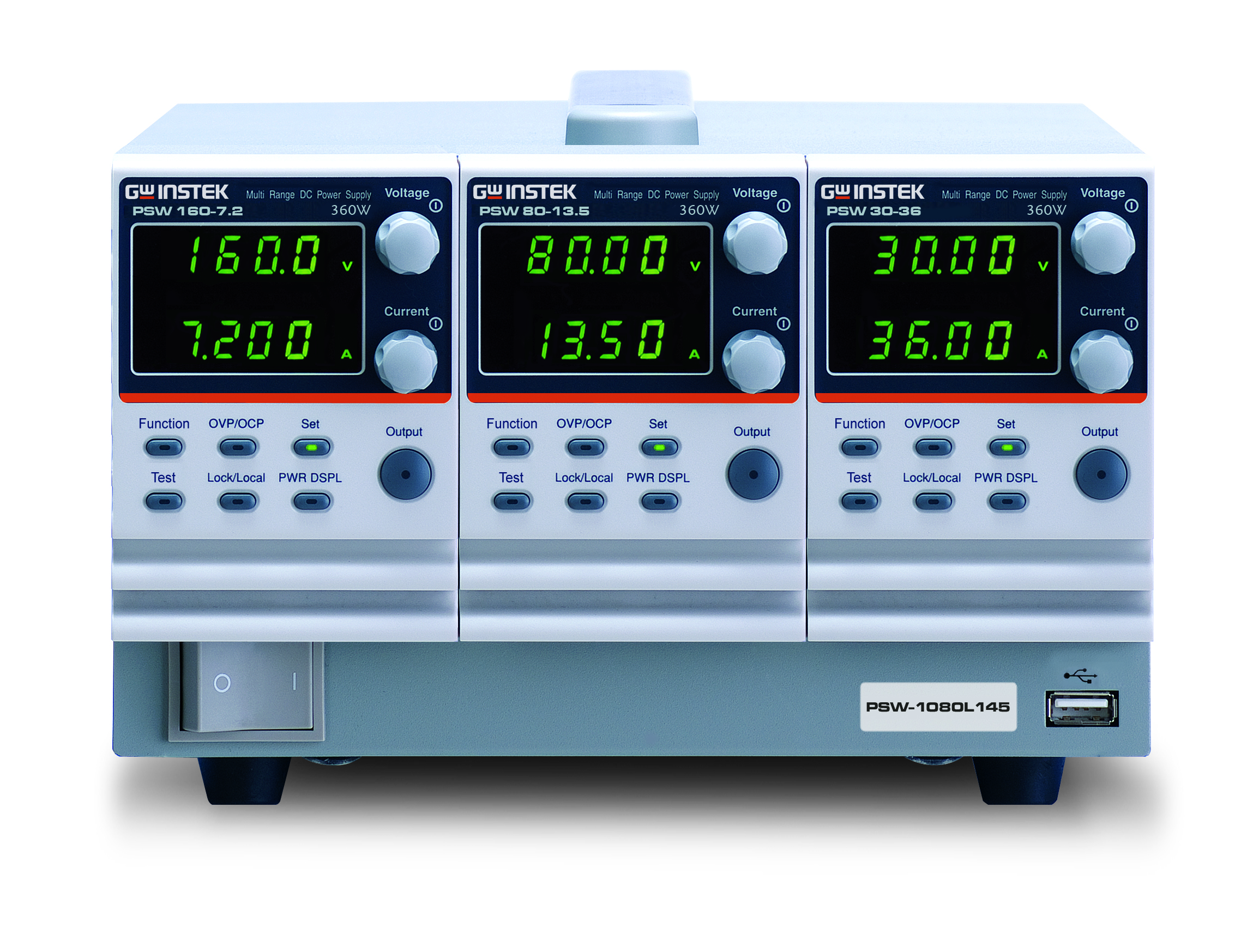
The PSW-Multi series Dual-channel PSW-720L14 Switching DC Power Supply is a high-performance, versatile power supply designed to meet the needs of complex testing and development environments. It features two independent, fully adjustable output channels that provide a stable DC voltage range from 0 to 72V and up to 14A of current, allowing precise power delivery for a wide range of electronic devices. The PSW-720L14 utilizes advanced switching technology to ensure high efficiency and low heat dissipation, making it ideal for continuous operation in labs or production testing. Its intuitive interface includes a large digital display for voltage and current monitoring, and it offers multiple protection features, including over-voltage, over-current, and over-temperature safeguards. This power supply is perfect for use in applications such as R&D, product testing, and system integration, where high accuracy, reliability, and flexibility are essential.
PSW-Multi Series Module Specifications
| Module Type | 1 | 2 | 4 | 5 | 6 | 8 | ||
| H/L Voltage Classicfication | — | L | L | L | L | H | H | |
| Rated output voltage | V | 30 | 40 | 80 | 160 | 250 | 800 | |
| Rated output current | A | 36 | 27 | 13.5 | 7.2 | 4.5 | 1.44 | |
| Rated output power | W | 360 | 360 | 360 | 360 | 360 | 360 | |
| Power ratio | — | 3 | 3 | 3 | 3.2 | 3.125 | 3.2 | |
| Constant Voltage Mode | 30-36 | 40-27 | 80-13.5 | 160-7.2 | 250-4.5 | 800-1.44 | ||
| Line regulation (*1) | mV | 18 | 23 | 43 | 83 | 128 | 403 | |
| Load regulation (*2) | mV | 20 | 25 | 45 | 85 | 130 | 405 | |
| Ripple and noise (*3) | p-p (*4) | mV | 60 | 60 | 60 | 60 | 80 | 150 |
| r.m.s. (*5) | mV | 7 | 7 | 7 | 12 | 15 | 30 | |
| Temperature coefficient | ppm/℃ | 100ppm/°C of rated output voltage, after a 30 minute warm-up | ||||||
| Remote snese compensation voltage (single wire) | V | 0.6 | 0.6 | 0.6 | 0.6 | 1 | 1 | |
| Rise time (*6) | Rated load | ms | 50 | 50 | 50 | 100 | 100 | 150 |
| No load | ms | 50 | 50 | 50 | 100 | 100 | 150 | |
| Fall time (*7) | Rated load | ms | 50 | 50 | 50 | 100 | 150 | 300 |
| No load | ms | 500 | 500 | 500 | 1000 | 1200 | 2000 | |
| Transient response time (*8) | ms | 1 | 1 | 1 | 2 | 2 | 2 | |
| Constant Current Mode | 30-36 | 40-27 | 80-13.5 | 160-7.2 | 250-4.5 | 800-1.44 | ||
| Line regulation (*1) | mA | 41 | 32 | 18.5 | 12.2 | 9.5 | 6.44 | |
| Load regulation (*9) | mA | 41 | 32 | 18.5 | 12.2 | 9.5 | 6.44 | |
| Ripple and noise | r.m.s. | mA | 72 | 54 | 27 | 15 | 10 | 5 |
| Temperature coefficient | ppm/℃ | 200ppm/°C of rated output current, after a 30 minute warm-up | ||||||
| Protection Function | 30-36 | 40-27 | 80-13.5 | 160-7.2 | 250-4.5 | 800-1.44 | ||
| Over voltage protection (OVP) | Setting range | V | 3-33 | 4-44 | 8-88 | 16-176 | 20-275 | 20-880 |
| Setting accuracy | ± (2% of rated output voltage) | |||||||
| Over current protection (OCP) | Setting range | A | 3.6-39.6 | 2.7-29.7 | 1.35-14.85 | 0.72-7.92 | 0.45-4.95 | 0.144-1.584 |
| Setting accuracy | ± (2% of rated output current) | |||||||
| Over temperature protection (OTP) | Operation | Turn the output off | ||||||
| Low AC input protection (AC-FAIL) | Operation | Turn the output off | ||||||
| Power limit (POWER LIMIT) | Operation | Over power limit. | ||||||
| Value (fixed) | Approx. 105% of rated output power | |||||||
| Analog Programming and Monitoring | 30-36 | 40-27 | 80-13.5 | 160-7.2 | 250-4.5 | 800-1.44 | ||
| External voltage control output voltage | at 23 °C ± 5 °C | Accuracy and linearity: ±0.5% of rated output voltage. | ||||||
| External voltage control output current | at 23 °C ± 5 °C | Accuracy and linearity: ±1% of rated output current. | ||||||
| External resistor control output voltage | at 23 °C ± 5 °C | Accuracy and linearity: ±1.5% of rated output voltage. | ||||||
| External resistor control output current | at 23 °C ± 5 °C | Accuracy and linearity: ±1.5% of rated output current. | ||||||
| Output voltage monitor | at 23 °C ± 5 °C | Accuracy: ±1% | Accuracy: ±2% | |||||
| Output current monitor | at 23 °C ± 5 °C | Accuracy: ±1% | Accuracy: ±2% | |||||
| Shutdown control | Turns the output off with a LOW (0V to 0.5V) or short-circuit | |||||||
|
Output on/off control |
Possible logic selections: Turn the output on using a LOW (0V to 0.5V) or short-circuit, turn the output off using a HIGH (4.5V to 5V) or open-circuit. Turn the output on using a HIGH (4.5V to 5V) or open-circuit, turn the output off using a LOW (0V to 0.5V) or short-circuit. | |||||||
| CV/CC/ALM/PWR ON/OUT ON indicator | Photocoupler open collector output; Maximum voltage 30V, maximum sink current 8mA. | |||||||
| Front Panel | 30-36 | 40-27 | 80-13.5 | 160-7.2 | 250-4.5 | 800-1.44 | ||
| Display, 4 digits Voltage accuracy | at 23 °C ± 5 °C; ± (0.1% + | mV | 20 | 20 | 20 | 100 | 200 | 400 |
| Current accuracy | at 23 °C ± 5 °C; ± (0.1% + | mA | 40 | 30 | 20 | 5 | 5 | 2 |
| Indications | GREEN LED’s: CV, CC, VSR, ISR, DLY, RMT, 20, 40, 60, 80, 100, %W, W, V, A | |||||||
| RED LED’s: ALM | ||||||||
| Buttons | Function, OVP/OCP, Set, Test, Lock/Local, PWR DSPL, Output | |||||||
| Knobs | Voltage, Current | |||||||
| USB port | Type A USB connector | |||||||
| Programming and Measurement (USB, LAN, GPIB) | 30-36 | 40-27 | 80-13.5 | 160-7.2 | 250-4.5 | 800-1.44 | ||
| Output voltage programming accuracy | at 23 °C ± 5 °C; ± (0.1% + | mV | 10 | 10 | 10 | 100 | 200 | 400 |
| Output current programming accuracy | at 23 °C ± 5 °C; ± (0.1% + | mA | 30 | 20 | 10 | 5 | 5 | 2 |
| Output voltage programming resolution | mV | 1 | 1 | 2 | 3 | 5 | 14 | |
| Output current programming resolution | mA | 1 | 1 | 1 | 1 | 1 | 1 | |
| Output voltage measurement accuracy | at 23 °C ± 5 °C; ± (0.1% + | mV | 10 | 10 | 10 | 100 | 200 | 400 |
| Output current measurement accuracy | at 23 °C ± 5 °C; ± (0.1% + | mA | 30 | 20 | 10 | 5 | 5 | 2 |
| Output voltage measurement resolution | mV | 1 | 1 | 2 | 3 | 5 | 14 | |
| Output current measurement resolution | mA | 1 | 1 | 1 | 1 | 1 | 1 | |
| Input Characteristics | 30-36 | 40-27 | 80-13.5 | 160-7.2 | 250-4.5 | 800-1.44 | ||
| Efficiency | 100Vac | % | 77 | 78 | 78 | 79 | 79 | 80 |
| 200Vac | % | 79 | 80 | 80 | 81 | 81 | 82 | |
| Input Characteristics | Dual Channel | Triple Channel | ||||||
| Norminal input rating | 100Vac to 240Vac, 50Hz to 60Hz, single phase | |||||||
| Input voltage range | 85Vac ~ 265Vac | |||||||
| Input frequency range | 47Hz ~ 63Hz | |||||||
| Maximum input current | 100Vac | A | 10 | 15 | ||||
| 200Vac | A | 5 | 7.5 | |||||
| Inrush current | Less than 50A | Less than 75A | ||||||
| Maximum input power | VA | 1000 | 1500 | |||||
| Power factor | 100Vac | 0.99 | ||||||
| 200Vac | 0.97 | |||||||
| Hold-up time | 20ms or greater | |||||||
| Interface Capabilities | Dual Channel | Triple Channel | ||||||
| USB | TypeA: Host, TypeB: Slave, Speed: 1.1/2.0, USB Class: CDC(Communications Device Class) | |||||||
| LAN | MAC Address, DNS IP Address, User Password, Gateway IP Address, Instrument IP Address, Subnet Mask | |||||||
| GPIB | Optional: GUG-001 (GPIB to USB Adapter) | |||||||
| Environmental Conditions | Dual Channel | Triple Channel | ||||||
| Operaing temperature | 0°C to 50 °C | |||||||
| Storage temperature | -25°C to 70 °C | |||||||
| Operating humidity | 20% to 85% RH; No condensation | |||||||
| Storage humidity | 90% RH or less; No condensation | |||||||
| Altitude | Maximum 2000m | |||||||
| General Specifications | Dual Channel | Triple Channel | ||||||
| Weight | main unit only | kg | Approx. 5.4kg | Approx. 7.7kg | ||||
| Dimensions | (W×H×D) | mm | 142 x 124 x 350 | 214 x 124 x 350 | ||||
| Cooling | Forced air cooling by internal fan | |||||||
| EMC | Complies with the European EMC directive for Class A test and measurement products | |||||||
| Safety | Complies with the European Low Voltage Directive and carries the CE-marking | |||||||
| Withstand voltage | Between input and chassis | No abnormalities at 1500 Vac for 1 minute | ||||||
| Between input and output | No abnormalities at 3000 Vac for 1 minute | |||||||
| Between output and chassis | No abnormalities at 500 Vdc for 1 minute for 30V, 40V, 80V, 160V models
No abnormalities at 1500 Vdc for 1 minute for 250V, 800V models |
|||||||
| Insulation resistance | Between input and chassis | 500 Vdc, 100 M Ω or more | ||||||
| Between input and output | 500 Vdc, 100 M Ω or more | |||||||
| Between output and chassis | 500 Vdc, 100 M Ω or more for 30V, 40V, 80V, 160V and 250V models
1000 Vdc, 100 M Ω or more for 800V models |
|||||||
Notes:
*1: At 85 ~ 132Vac or 170 ~ 265Vac, constant load.
*2: From No-load to Full-load, constant input voltage. Measured at the sensing point in Remote Sense.
*3: Measure with JEITA RC-9131B (1:1) probe
*4: Measurement frequency bandwidth is 10Hz to 20MHz.
*5: Measurement frequency bandwidth is 5Hz to 1MHz.
*6: From 10% to 90% of rated output voltage, with rated resistive load.
*7: From 90% to 10% of rated output voltage, with rated resistive load.
*8: Time for output voltage to recover within 0.1% + 10mV of its rated output for a load change from 50 to 100% of its rated output current.
*9: For load voltage change, equal to the unit voltage rating, constant input voltage.


ACCESSORIES
Power Cord x1(Region dependent)
GTL-123 Test Lead x 1 (30V/40V/80V/160V One low voltage module for each channel)
GTL-240 USB Cable”L” Type x1
PSW-004 Basic Accessories Kit x1(30V/40V/80V/160V low voltage module)
PSW-008 Basic Accessories Kit x1(250V/800V high voltage module)
PSW-009 Output terminal cover(30V/40V/80V/160V low voltage module)
PSW-011 Output terminal cover(250V/800V high voltage module)
PSW-012 High voltage output terminal(250V/800V high voltage module)
OPTIONAL ACCESSORIES
PSW-001 Accessory Kit
PSW-002 Simple IDC Tool
PSW-003 Contact Removal Tool
PSW-010 Large filter (for PSW 720W/1080W models)
GUG-001 GPIB to USB Adaptor
GRA-410-J Rack Mount Kit(JIS)
GRA-410-E Rack Mount Kit(KIA)
GET-001 Extended Terminal with max. 30A(30V/40V/80V/160V low voltage)
GET-002 Extended Terminal with max. 10A(250V/800V high voltage module)
GET-005 Extended European Terminal with max. 20A(30V/40V/80V/160V low voltage module)
GTL-130 Test Lead: 2x red, 2x black(250V/800V high voltage module)
GTL-248 GPIB Cable, 2000mm
GUR-001A USB TO RS-232 Cable (M3), 3000mm
GUR-001B USB TO RS-232 Cable (#4-40 UNC), 3000mm
