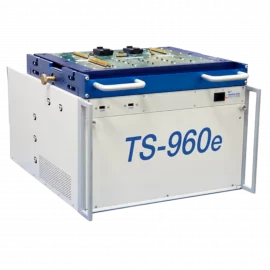
TS-960e-5G Specifications
| mmWave Tests | |
|---|---|
| Tx / Rx Tests | S-Parameter Measurement (Insertion / Return Loss) S12, S21, S11, S22 |
| TS-960e-5G PXIe Chassis | |
| Number of Slots | 1 controller, 8 PXI-1, 8 Hybrid, 4 PXIe |
| System CPU (Embedded) | Intel Core i7, 2.4 GHz, single slot controller 4×4 PCIe bus configuration 8 GB of RAM |
| System Hard Disk | 320 GB (min) |
| Cooling | (4) 100 CFM fans for system cooling. Integrated temperature monitoring via an on-board microcontroller with audible and software notification when preset temperature limits are exceeded. Fan speed control and monitoring is automatic and can be controlled / monitored via the GxChassis software. |
| PXI Clock | Integrated 10 MHz PXI clock with auto-detect function. Presence of an external 10 MHz PXI clock will disable the internal clock. PXI clock is distributed to all peripheral slots. Optional external clock via slot 2 |
| Temperature Monitoring | Per slot monitoring, 1 reading/sec/slot 4 second moving average value User selectable alarm criteria:
Accuracy: ± 2 °C |
| Power Supply Monitoring | Monitored voltages: 3.3, 5, +12, -12, VIO value Accuracy: ± 2% of reading |
| PXI Triggers | Slots: 2 – 21 Number: 8 per segment Software controlled segment mapping supports:
|
| PXI Clock and Synch Resources |
Integrated 10 and 100 MHz clock with an auto-detect function. Presence of an external 10 MHz PXI clock will synchronize the 100 MHz clock to the external 10 MHz source 100 MHz clock accuracy: ± 30 ppm Synchronization signals: SYNC100 & SYNC_CTRL |
| External 10 MHz Clock Input | An external 10 MHz clock source (TTL level) can be provided via a rear panel BNC or via a PXI Express System Timing Controller |
| 10 MHz Clock Output | 10 MHz output is available via a rear panel BNC connector, TTL compatible level |
| PXIe System Power | 1600 W |
| PXIe Chassis Input AC Power | 120 VAC, ±15%; 20 A max (PFC) 240 VAC, ±10%; 10 A max (PFC) 47 Hz to 440 Hz |
| Dynamic Digital I/O Subsystem | |
| Number of Digital I/O and PMU Channels | 64 (base configuration) |
| Maximum Channel Configuration | 256 channels |
| Maximum Clock Rate | 100 MHz |
| Digital Test Modes | Stimulus / response Real-time compare |
| Vector Memory | 64 Mb / channel |
| Real Time Compare Record Memory | 1,024 (records data and program steps) |
| Drive Voltage Range | -2 V to +7 V, Drive Hi & Drive Lo, maximum swing is 8 V |
| Sense Voltage Range | -2 V to +7 V, Sense Hi & Sense Lo |
| Programmable Pull-Up / Pull-Down Current Source / Sink | ±24 mA, programmable on a per channel basis, V commutate range: -2 V to +7 V, programmable on a per channel basis |
| High and Low Commutation Voltage Range | VCLo: -2 V to +5 V VCHi: 0 V to +7 V |
| Voltage Clamp Accuracy | ±100 mV |
| Parametric Measurement (PMU) | |
| Number of Parametric Measurement Units | 32, one per channel 4, one per auxiliary channel (for timing /control & static I/O functions) |
| Configurations | Force Voltage/Measure Current (FVMI) Force Current/Measure Voltage (FIMV) Force Voltage/Measure Voltage (FVMV) Force Current/Measure Current (FIMI) |
| Force Voltage Range | -1.5 V to +7 V |
| Force Voltage Accuracy | ±20 mV |
| Force Voltage Resolution | 16 bits |
| Force Current Ranges | ±32 mA, ±8 mA, ±2 mA, ±512 uA, ±128 uA, ±32 uA, ±8 uA, ±2 uA FS |
| Force Current Accuracy: Compliance Range: +1.75 V to +7 V @ 32 mA -1.5 V to +7 V @ no load |
±120 uA, 32 mA range ±40 uA, 8 mA range ±5 uA, 2 mA range ±1.2 uA, 512 uA range ±600 nA, 128 uA range ±160 nA, 32 uA range ±80 nA, 8 uA range ±20 nA, 2 uA range |
| Current Measurement Accuracy (60 Measurements / Sec) Compliance Range: +1.75 V to +7 V @ 32 mA -1.5 V to +7 V @ no load |
±120 uA, 32 mA range ±40 uA, 8 mA range ±5 uA, 2 mA range ±1.2 uA, 512 uA range ±600 nA, 128 uA range ±160 nA, 32 uA range ±80 nA, 8 uA range ±20 nA, 2 uA range |
| Measure Voltage Range | -2 V to +7 V |
| Measure Voltage Accuracy | ±1 mV (measurement rate < 200 measurements / sec) |
| Static Digital Instrument | |
|---|---|
| Number of Static Digital I/O Channels | 64, expandable to 128 48 Input / Output ( programmable I/O in groups of eight) 16 inputs for fixture ID |
| Logic Levels | LVTTL compatible |
| Source / Sink Current | 24 mA (max) |
| User Power | |
|---|---|
| Source / Measure Unit (SMU) | 4-channel, 4 quadrant operation, isolated outputs, common ground, with remote sense |
| Programmable Voltage Range | 0 to ±20 V |
| Output Voltage Accuracy | ±0.05% of programmed value + 2 mV |
| Output Noise | < 20 mV p-p, 20 MHz BW, full load |
| Output Current | ±2.5 uA to ±250 mA in decade ranges, any one channel can supply up to 1A |
| Output Current Accuracy | ±0.05% of programmed value + 0.05% of FS |
| Voltage Measurement Accuracy | ±0.03% of programmed value + 2 mV |
| Current Measurement Accuracy | Ranges: 2.5 uA to 250 mA in decades Accuracy: ±0.05% of reading + 0.05% of FS range |
| Measurement Resolution | Programmable, 18 to 24 bits |
| RF Vector Network Analyzer Options | |
| Keysight Technologies | M9807, 2 port VNA, 40 GHz, PXIe M9808A, 2 port VNA, 53 GHz, PXIe |
| TS-960e-5G Receiver Interface | |
| Type | Modular, pogo-pin and blind-mate RF interface |
| Interfaces |
(Weinschel Planar Blind-Mate, 2.92mm (SMK) |
| Environmental / Physical | |
|---|---|
| Operating Temperature | 0 °C to +50 °C |
| Storage Temperature | -20 °C to +60 °C |
| Relative Humidity (Non-Condensing) |
90% |
| Altitude | 30,000 ft |
| Weight | 125 lbs, core system |
| Overall Size | 24″ D x 22″ W x 17″ H |
| Manipulator Option | Reid-Ashman OM-1069 |
Note: Specifications are subject to change without notice.