- 17 Channels
- Hipot/Leakage Current
- Insulation Resistance
- Winding Layer short Test
- Three-Phase Current Balance Test(Option)
- Steering test
- Inductance Test
- It can test multiple sets of DUTs simultaneously
- 4-Wire DC Resistance measurement will be more accurate than others
- The Impulse/Surge with waveform comparison is a non-destructive analysis
- Chinese/English screen could be switched arbitrarily
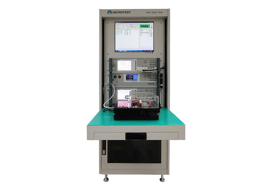

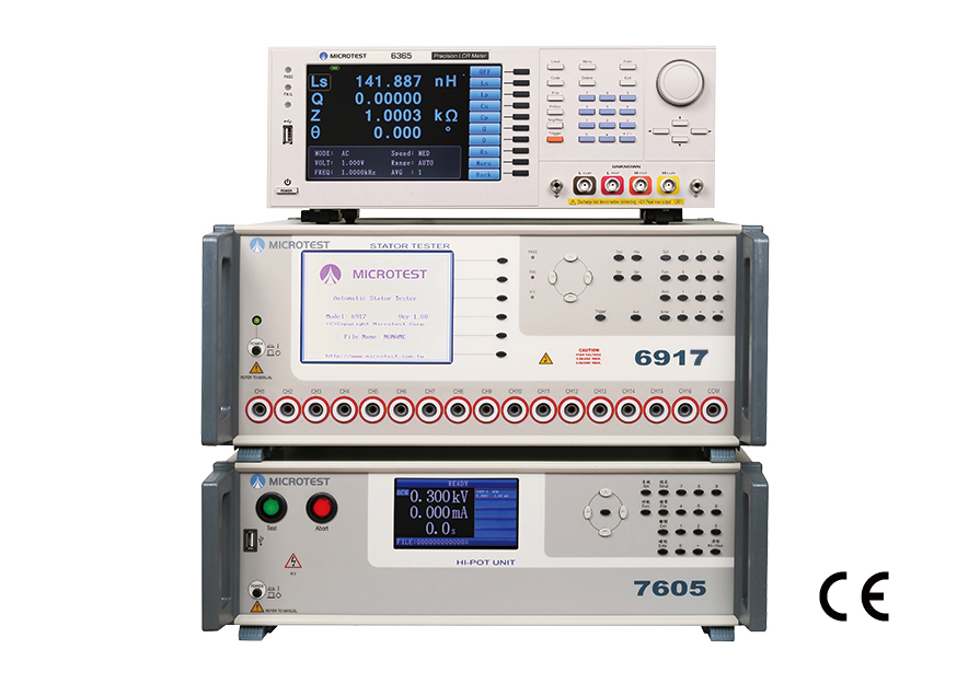
MICROTEST MT-6917 Motor Stator Testing System integrates the Interlayer Short-Circuit Tester (6917), the High Voltage Withstand Tester (7605), and the LCR Tester (6365), with the 6917 serving as the main controller. It is capable of setting up all measurement parameters and provides 17 test channels. The external PC software allows for real-time data retrieval from the 6917, generating reports, or directly uploading test results to a database.
This all-in-one integrated system covers safety compliance, high-voltage insulation, and coil interlayer short-circuit testing for motor stators. It can measure motor stator polarity (rotation test) using precise four-wire resistance measurement technology. Additionally, it supports three-phase current balance testing (optional). The system can be equipped with PC connectivity software for data storage and can be configured with PLC control. Customized test fixtures can be provided for specific customer stators. Furthermore, it offers an optional LCR Meter for measuring the stator’s inductance values with a test frequency range of 10Hz to 200kHz, supporting three-phase balanced inductance testing.
Specifications
Selection
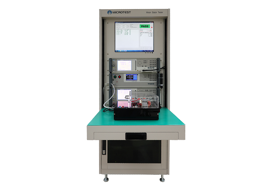
MICROTEST stator testing solution can be tailored into a complete testing system based on different requirements. Firstly, you can evaluate whether to opt for a rack-mounted or desktop configuration, as well as whether to incorporate PC connectivity.
| System | Benchtop | Rack |
|
|
 |
| Evaluate whether to include PC connectivity software. | ||
| Function | Operate directly on the instrument | PC Link |
| Production Traceability Management – Implementing Bar Code/Label Printer/Laser Engraver | / | ● |
| Store test file sets | 100 sets (existing instruments) | Unlimited (according to PC memory) |
| Sharing test files between devices | Unable to share, recreate the file | Share through PC software |
| Accessing test data | / | Transfer test data to the PC via the RS-232 interface |
| Uploading test data to a cloud database | / | ● |
| User Permission Management” or “User Access Control | /
|
Supports permission management, configuration through Engineering Mode |
| CPK Report | /
|
|
| Customized CPK Report According to Customer Requirements | / | 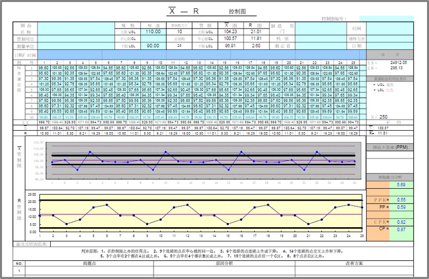 |
SPEC
| Model | MT-6917 | MT-6913 | MT-6913L | MT-6910 |
| Test Channel | 17 | 13 | 13 | 8 |
| DCR Range | 0.1mΩ-100kΩ | 0.1mΩ-100kΩ | 0.1mΩ-150Ω | 0.1mΩ-100kΩ |
| DCR Accuracy | Low Resistance
0.1mΩ-1Ω ±(0.2%±1mΩ) |
Low Resistance
0.1mΩ-1Ω ±(0.2%±1mΩ) |
Low Resistance
0.1mΩ-200mΩ ±(0.1%±0.5mΩ) |
Low Resistance
0.1mΩ-1Ω ±(0.2%±1mΩ) |
| High Resistance
1Ω-100KΩ ±0.1%
|
High Resistance
1Ω-100KΩ ±0.1%
|
High Resistance
200mΩ-1Ω ±(0.1%±2mΩ 1Ω-150Ω ±0.5% |
High Resistance
1Ω-100KΩ ±0.1%
|
SPEC
| Model | MT-6917 |
| DC Resistance Test (6917) | |
| DCR Range | 0.1mΩ-100kΩ |
| Measuring Mode | 4-Wire |
| Safety Hi pot Test (7605) | |
| AC Output Voltage | 100V-3000V |
| AC Leakage Current | 0.001mA-10mA |
| AC Arcing Detection | Detect gears from 0-9 |
| DC Output Voltage | 100V-3000V |
| DC Leakage Current | 0.001mA-5mA |
| DC Arcing Detection | Detect gears from 0-9 |
| IR Output Voltage | 100V-1000V |
| Insulation Resistance | 1-9999MΩ |
| Measuring Time | 0.1-99.9s Continuously adjustable |
| Voltage Accuracy | ±(3% of setting+5V) |
| Impulse Winding Test (6917) | |
| Impulse Voltage (programmable) | 200V-3000V |
| Impulse Voltage Accuracy | ±2% |
| Total area comparison | When layer short happened, the loss of power on coil increase, the resonance damping coefficient increase, resonance amplitude decrease, the total area decrease. These are the basic parameters we check layer short.
By calculating and comparing the deference of area between golden sample and DUT. |
| Differential area comparison | Add up the difference between normal wave and DUT wave call “ Area differential”. When layer short happened, the inductance reduce(similar the transformer). The wave phase change and the area differential also change. This will show “fail” on the instrument. However, the parameter might cause deviation because of the deviation of inductance, resonance phase shift. (Silicon steel product such as motor and traditional transformer is not suitable)By calculating and comparing the deference of area between golden sample and DUT. To determine the degree of waveform overlap. Compare the inductance by this. |
| Wave comparison | Set a acceptable wave range, if the DUT’s wave is in this range shows “pass” otherwise, “fail” This parameter can judge both amplitude and phase of resonance wave. This can increase the detection capability of layer short. |
| Corona comparison | In pulse test, the insulation defect will cause discharge and create corona. This function is able to count the times that corona happened base on the degree of deviation. Detect the discharge phenomenon on the coil. |
| Flat comparison | If the layer short happened, the waveform will tremble. Therefore, the instrument will quantize and compared it. |
| Inductance Measurement (Option LCR Meter 6365) | |
| Inductance Ranges | 0.1nH – 99.999KH |
| Test Frequency | 10Hz-200kHz |
| Frequency Output Accuracy | ±0.01% |
| Frequency Resolution | 5 Digits |
| AC Drive Level | 10mV to 2Vrms (1m Vrms resolution) |
| Basic Accuracy | ±0.1% |
| Three-phase Inductance Balance Test | Comparison Mode
|
SYSTEM
| Test fixture | According to the test requirements | |
| Indicator | Pass/Fail Screen Diaplay/Sound | |
| Built-in Storage | Storage of 100 rewritable data sets | |
| Operation | Manual, RS-232 | |
| Power Supply | Voltage | 90-132Vac or 198-264Vac |
| Frequency | 50/60Hz | |
| Power consumption | 300VA | |
| Environment | Temperature | 10℃-40℃ |
| Humidity | 20-90%RH | |
| Display | 6917 | 5.7″ dot-matrix display (320*240) |
| 7605 | 4.3″ TFT LCD (480*272) | |
| 6365 | 7.0″ TFT (800*480) | |
| Dimension
(W*H*D) |
6917 | 435x190x522mm |
| 7605 | 435x145x522mm | |
| 6365 | 435x145x522mm | |
| Weight | 6917 | 15 Kg |
| 7605 | 14 Kg | |
| 6365 | 3 Kg | |
| Interface | RS-232 | |


Standard Accessories
| Power Cord | |
| RCA adapter |  |
| RS-232 Cable | |
| Remote Cable (25F-25F) | |
| D-Sub footswitch (F760001) | |
Optional Accessories
| PC Link Software | |
| Customized cabinet | |
| Test Fixture | 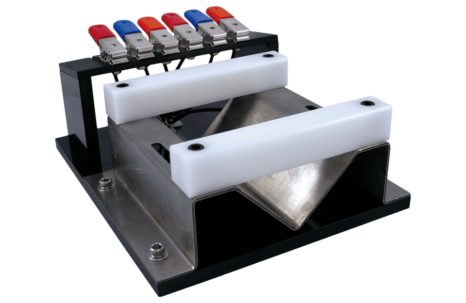 |
