- 200/100/70MHz bandwidth selections: 2 or 4 channels
- MSO-2000E equips with a 16-channel logic analyzer
- MSO-2000EA equips with a 16-channel logic analyzer and a dual channel 25MHz arbitrary waveform generator
- Real time Sampling rate for each channel is 1GSa/s (2-channel models);Maximum real time Sampling rate is 1 GSa/s (4- channel models)
- Maximum 10M memory depth and VPO waveform display technology
- Waveform update rate up to 120,000 wfms/s
- 8 ” WVGA TFT LCD screen display
- Free Frequency Response Analyzer Software
- Maximum 1M FFT provides higher frequency domain resolution measurements
- High Pass, Low Pass and Band Pass Filter Functions
- 29,000 segmented memory sections and waveform search function
- I2C/SPI/UART/CAN/LIN serial bus trigger and decoding functions
- Data log function is able to track signal changes up to 100 hours
- Network storage function
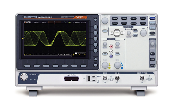
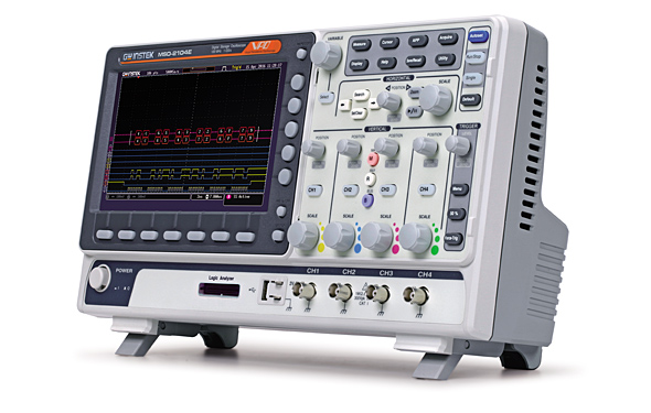
Economical and Multi-Functional MSO
The MSO-2000 series is a mixed-signal oscilloscope, which offers dual analog channels + 16 digital channels or 4 analog channels + 16 digital channels. The MSO-2000 series includes MSO-2000E and MSO-2000EA. MSO-2000E has a built-in 16-channel logic analyzer and MSO-2000EA has a built-in 16-channel logic analyzer and a dual channel 25MHz arbitrary waveform generator. The entire series features bandwidth selections of 200MHz, 100MH, and 70MHz. Dual analog channel models provide 1GSa/s real-time sampling rate per channel; four analog channel models provide 1GSa/s maximum real-time sampling rate. The 8-inch 800*480 TFT LCD and the minimum 1mV/div vertical range allow the MSO-2000 series to measure complex feeble signals and clearly display measurement results.
For analog channels, the MSO-2000 series provides 10M long memory for users to completely retrieve and analyze waveforms. Users, based upon the application requirements, can select 1k, 10k, 100k, 1M or 10M memory depth. Short memory depth collocating with the high sampling rate allows users to observe fast-changing waveforms and, on the other hand, long memory depth aims for continuously changing waveforms. The MSO-2000 series is equipped with waveform search and segmented memory functions to expand the flexible applications of 10M long memory. The segmented memory can be divided the maximum into 29,000 sections for users to bypass any unimportant waveforms so as to swiftly search all required waveforms. With the segmented memory function, more meaningful waveforms can be saved and target waveforms can be displayed rapidly. Users, by using the waveform search function, can rapidly search desired waveforms according to the required trigger conditions.
16-channel logic analyzer has a memory depth of 10Mpts per channel, which can retrieve more and longer digital signals as well as clearly display digital signals to obtain sufficient information for analysis. The minimum input swing of logic analyzer represents the minimum operating voltage of ±250 mV, which demonstrates that digital channels are highly sensitive with respect to input. The standard bus trigger and decoding functions include serial and parallel bus such as I2C, SPI, UART (RS232/422/485) and CAN/LIN bus for automotive communications. The parallel bus function is only for digital channels. Bus waveforms can be triggered and decoded in real time. The MSO-2000 series offers complete analysis and debugging capabilities with the economical pricing.

CAN Bus Trigger and Decode
In addition to a 16-channel logic analyzer, MSO-2000EA has a built-in dual channel 25MHz arbitrary waveform generator with the modulation capability and also features 14 bits vertical resolution; sample rate of 200MSa/s; 5 standard output waveforms (Sine, Square, Pulse, Ramp, DC, Noise) and 7 user-defined waveforms (Sinc, Gaussian, Lorentz, Exponential Rise, Exponential Fall, Haversine, Cardiac); AM/FM/FSK modulation and sweep function. The user friendly interface is the ideal choice for applications such as circuit simulation and education tests.

Dual Channel Arbitrary Waveform Generator
Model Variants
- MSO-2072E(A)
- 2 channels + External trigger
- 70 MHz bandwidth
- 5 ns rise time
- MSO-2074E(A)
- 4 channels
- 70 MHz bandwidth
- 5 ns rise time
- MSO-2102E(A)
- 2 channels + External trigger
- 100 MHz bandwidth
- 3.5 ns rise time
- MSO-2104E(A)
- 4 channels
- 100 MHz bandwidth
- 3.5 ns rise time
- MSO-2202E(A)
- 2 channels + External trigger
- 200 MHz bandwidth
- 1.75 ns rise time
- MSO-2204E(A)
- 4 channels
- 200 MHz bandwidth
- 1.75 ns rise time
- Bandwidth Limit Options:
- 20 MHz limit available on all models
- 100 MHz limit selectable on 200 MHz models
Vertical System
- Resolution: 8-bit
- Vertical Sensitivity: 1 mV/div ~ 10 V/div
- Input Coupling: AC, DC, GND
- Input Impedance: 1 MΩ // 16 pF (approx.)
- DC Gain Accuracy:
- ±3% (≥ 2 mV/div)
- ±5% (1 mV/div)
- Polarity: Normal & Invert
- Max Input Voltage: 300 Vrms, CAT I
- Offset Range:
- 1 mV–20 mV/div: ±0.5 V
- 50 mV–200 mV/div: ±5 V
- 500 mV–2 V/div: ±25 V
- 5 V–10 V/div: ±250 V
Waveform Math and Processing
- Operations: +, −, ×, ÷, FFT, FFTrms, User-defined expressions
- FFT: 1 Mpts with selectable window (Rectangular, Hamming, Hanning, Blackman-Harris)
- FFT Scale: Linear RMS or dBV RMS
Trigger System
- Sources: CH1, CH2, CH3, CH4, EXT, Line (*EXT only on 2ch models)
- Modes: Auto (with Roll mode ≥100 ms/div), Normal, Single Sequence
- Types: Edge, Pulse Width (Glitch), Video, Runt, Rise/Fall (Slope), Alternate, Timeout, Event Delay (1–65535 events), Time Delay (4ns–10s), Bus
- Holdoff Range: 4ns to 10s
- Coupling: AC, DC, LF reject, HF reject, Noise reject
- Sensitivity: 1 div
External Trigger
- Range: ±15 V
- Sensitivity:
- DC–100 MHz: ~100 mV
- 100–200 MHz: ~150 mV
- Impedance: 1 MΩ ±3%, 16 pF
Horizontal System
- Time Base Range: 1 ns/div to 100 s/div (1-2-5 increments)
- ROLL Mode: 100 ms/div to 100 s/div
- Pre-trigger: Max 10 divisions
- Post-trigger: Max 2,000,000 divisions
- Time Base Accuracy: ±50 ppm (≥1 ms interval)
- Real-Time Sample Rate:
- Max 1 GSa/s (4ch model total)
- 1 GSa/s per channel (2ch model)
- Record Length: Max 10 Mpts
- Acquisition Modes: Normal, Average (2 to 256), Peak Detect (2 ns typical), Single
X-Y Mode
- X-axis Input: CH1 or CH3* (*4ch only)
- Y-axis Input: CH2 or CH4* (*4ch only)
- Phase Shift: ±3° at 100 kHz
Cursors and Measurement
- Cursors: Amplitude, Time, Gating (s, Hz, °, %)
- Auto Measurements (38 types): Includes Vpp, Max, Min, Mean, RMS, Rise/Fall Time, Frequency, Duty, Pulses, Edges, Overshoot, Phase, etc.
Control Functions
- Auto Counter: 6-digit, 2 Hz to full bandwidth
- Autoset: Full channel setup with Undo
- Save Settings: 20 setups
- Save Waveforms: 24 sets
Display
- Screen: 8” TFT LCD, WVGA (800 × 480)
- Interpolation: Sin(x)/x
- Display Modes: Dots, Vectors, Variable Persistence (16 ms to 4 s), Infinite
- Update Rate: Max 120,000 wfms/s
- Graticule: 8 × 10 divisions
- Display Formats: YT and XY
Connectivity
- USB: 1x USB 2.0 Host, 1x USB 2.0 Device
- Ethernet (LAN): RJ-45, 10/100 Mbps with HP Auto-MDIX
- Go-NoGo Output: 5V Max/10mA, TTL open collector
- Security: Kensington lock slot
Logic Analyzer (MSO Models Only)
- Channels: 16 digital (D0–D15)
- Sample Rate: 1 GSa/s per channel
- Bandwidth: 200 MHz
- Record Length: 10 Mpts per channel
- Trigger Types: Edge, Pattern, Pulse Width, Serial (I2C, SPI, UART, CAN, LIN), Parallel Bus
- Threshold Groups: D0–D3, D4–D7, D8–D11, D12–D15
- Threshold Levels: TTL, CMOS (5V/3.3V/2.5V), ECL, PECL, 0V, User-defined (±5V)
- Max Input Voltage: ±40 V
- Min Voltage Swing: ±250 mV
- Input Impedance: 101 kΩ // 8 pF
- Vertical Resolution: 1-bit
AWG (MSO-2000EA Models Only)
- Channels: 2
- Sample Rate: 200 MSa/s
- Vertical Resolution: 14 bits
- Max Frequency: 25 MHz
- Waveforms:
- Standard: Sine, Square, Pulse, Ramp, DC, Noise
- ARB: Sinc, Gaussian, Lorentz, Exp Rise/Fall, Haversine, Cardiac
- Output Range:
- 20 mVpp – 5 Vpp (High-Z)
- 10 mVpp – 2.5 Vpp (50 Ω)
- Output Accuracy: 2% at 1 kHz
- Offset Range:
- ±2.5 V (High-Z)
- ±1.25 V (50 Ω)
Waveform Specs
- Sine:
- 100 mHz to 25 MHz
- Flatness: ±0.5 dB (<15 MHz), ±1 dB (15–25 MHz)
- THD: 1%, Harmonic/Non-harmonic Distortion: −40 dBc
- Square/Pulse:
- 100 mHz to 15 MHz
- Rise/Fall Time: <15 ns, Overshoot <3%, Duty Cycle: 0.4%–99.6%
- Jitter: 500 ps, Min Pulse Width: 30 ns
- Ramp:
- 100 mHz to 1 MHz
- Linearity: 1%, Symmetry: 0–100%
Frequency Response Analysis (MSO-2000EA Only)
- Dynamic Range: >80 dB (typical)
- Input/Output Sources: CH1/2 (CH3/4 on 4ch models)
- Frequency Range: 20 Hz to 25 MHz
- Test Points: 10–90 points per decade
- Test Amplitude: 20 mVpp–5 Vpp (High-Z)
- Output: Logarithmic gain & phase plot
- Manual Markers: 2 pairs tracking gain/phase
- Plot Scaling: Auto-scaled
Miscellaneous
- Multilingual Menu: Available
- Operating Environment:
- Temp: 0°C to 50°C
- RH: ≤80% @ ≤40°C, ≤45% @ 41–50°C
- On-line Help: Available
- Time Clock: Date/time for saved data
- Dimensions: 384 × 208 × 127.3 mm
- Weight: 2.8 kg


Accessory
- User Manual CD x1, Power Code x1
GTL-16E
16-Channel Logic Analyzer Probe - GTP-070B-4
70MHz(10:1/1:1)Switchable passive probe for MSO-2072E(A)/2074E(A)(one per channel) - GTP-100B-4
100MHz(10:1/1:1)Switchable passive probe for MSO-2102E(A)/2104E(A)(one per channel) - GTP-200B-4
200MHz(10:1/1:1)Switchable passive probe for MSO-2202E(A)/2204E(A)(one per channel)
Optional Accessories
- GTL-16E
16-Channel Logic Analyzer Probe - GRA-426
Rack Adapter Panel - GAK-003
50 Impedance Adapter - GSC-008
Soft Carrying Case - GTL-246 USB Cable, USB 2.0, A-B Type, 1200mm
- GDB-03 Oscilloscope Education & Training Kit
- GTP-033A Oscilloscope Probe, 35MHz 1:1 Passive Probe, BNC(P/M)
- GCP-201 Probe Clip, 20PCS
- GCP-300 Current Probe, DC ~ 300kHz, 200A
- GCP-500 Current Probe, DC ~ 500kHz, 150A
- GCP-1000 Current Probe, DC ~ 1MHz, 70A
- GCP-1030 Current Probe, DC~100MHz, 30Arms, Current Probe
- GCP-206P Current Probe – Power Supply, 2 Channel Power Supply for GCP-530/1030
- GCP-425P Current Probe – Power Supply, 4 Channel Power Supply for GCP-530/1030
- GCP-530 Current Probe, DC~50MHz, 30Arms, Current Probe
- GDP-025 Differential Probe, 25M High Voltage Differntial Probe
- GDP-050 Differential Probe, 50M High Voltage Differntial Probe
- GDP-100 Differential Probe, 100M High Voltage Differntial Probe
