DCT | Test and Measurement

Welcome to our new site! Feel free to report any issues, contact us at [email protected]

ILA1001 Cellular Power Amplifier Module

ILA1001 Cellular Power Amplifier Module

  • LTE-700 Band Support Specifically designed for the 728–757 MHz frequency range, ideal for LTE-700 infrastructure applications.

  • High Output Power Delivers up to 2.5 W output with approximately 41 dB gain for enhanced signal strength and coverage.

  • Efficient Design Uses advanced LDMOS technology to ensure high efficiency, low distortion, and stable performance.

  • Compact & Integrable Measures just 120 × 110 × 25 mm, making it easy to install in repeaters, small cells, and communication modules.

  • Reliable Operation Operates on 28 V DC with built-in protections and RoHS-compliant construction for long-term dependability.

Send Enquiry

Key Features

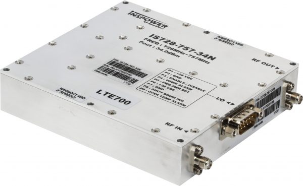
  • Designed for LTE-700 applications (728–757 MHz frequency range)

  • Output power up to 2.5 W (approximately +34 dBm)

  • High gain of approximately 41 dB

  • Based on high-efficiency LDMOS technology

  • Operates on 28 V DC supply at ~1.1 A

  • Optimized for 50-ohm RF systems

  • Compact module size: 120 × 110 × 25 mm

  • Narrowband design for low distortion and high linearity

  • Ideal for LTE repeaters, small cells, and IoT gateways

  • Built-in protection features for stable and reliable operation

  • RoHS-compliant design for environmentally responsible manufacturing

The ILA1001 Cellular Power Amplifier Module is a precision-engineered RF amplifier tailored specifically for LTE‑700 applications, covering the 728 MHz to 757 MHz frequency band. Leveraging high-performance LDMOS technology, it delivers up to 2.5 W output power and achieves an impressive gain of approximately 41 dB. The module is optimized for 50 Ω systems and operates efficiently on a standard 28 V DC supply at around 1.1 A, making it suitable for compact infrastructure setups with limited power availability.

Engineered for dependable performance, the ILA1001 ships in a compact 120 × 110 × 25 mm housing that simplifies integration into LTE repeaters, small-cell base stations, and IoT gateway systems targeting LTE‑700 deployment. Its narrow-band design ensures enhanced linearity and power efficiency, minimizing distortion across the operating band. As part of Inspower’s modular amplifier lineup, the ILA1001 delivers consistent and robust RF amplification with built-in thermal and electrical safeguards, backed by RoHS-compliant manufacturing practices.

Electrical Specifications

Parameters Specifications Remark
Operating Frequency 728 ~ 757MHz
Output Power (Linear) +34dBm Min
Small Signal Gain 40dB Min, 41dB Typical, 42dB Max In Band
Small Signal Gain Flatness 1dBp-p Max Over temperature
Gain Variation Over operation Temp ±1 dB
IMD3 & IMD5 product level

@ Pout per Tone= 25dBm to 31dBm


-20dBm


2 tones 2MHz spacing


IMD3 & IMD5 product level of -20dBm

@ 34dBm Pout composite vs. Tone spacing


1MHz Min , 29MHz Max

Any frequency location for 2tone 2MHz spacing.

Any 2 tone spacing 1MHz – 29MHz around band center.

IMD3, 5 product band of interest is

698-787MHz

Spurious emission -32dBm Max 1.  With CW tone

2.  Without input signal


LTE

@ 34dBm output

EVM 2% Test Model: E.T.M 3.1 Down Link (EVM : test for all LTE BW) Test EVM and SEM for 1.4 &

10MHz BW located at center,

right edge and left edge of band.

Frequency Error ±0.01ppm
Spectrum Emission Mask Per ETSI TS 136 106 V11.1.0(2013-02)
ACPR ±5MHz 35dBc Test ACPR or 5MHZ BW Located at center, right edge and

Left edge of band.

±10MHz 35dBc
2nd Harmonic – 40dBc
Input / Output VSWR 1.2:1Typ, 1.5:1Max S11 / S22
Noise Figure 10 dB Typ

15 dB Max


Parameters Specifications Remark
Turn-on time 300 mS From DC power On or Enable
Forward (FWD) Power Monitoring:

@33dBm CW 1FA 100mv/dB

3.95V Min , 4V Typ ,4.05V Max True RMS detector.
Operating Voltage 27V Min, 28V Typ, 30V Max
No Damage Supply Voltage 32V This parameter was updated
Supply Current @ Pout = 34dBm / 1CW 1.1A Max This parameter was updated
Supply Current @ Pout = 38dBm / 1CW 1.3A Max This parameter was updated
Supply Current @ Pout = 10W / 1CW 1.7A Max This parameter was updated


Mechanical Specifications


Parameter Specifications Remark
Dimensions (W x D x H) 120 * 110 * 25 mm
Weight 0.6kg
RF Connectors In/Out SMA – Female
Monitoring/DC Connectors D-sub, 9 Pins,4 – 40 screw
Cooling External Heat sink (not included)

Environmental Characteristics


Parameters Specifications Remark
Case Temperature for operating without damage -40°C to +85°C
Case Temperature for operating with full performance -30°C to +80°C
Storage Temperature -40°C to +85°C
Relative humidity w/o condensation 95%
 

Shock & Vibration

According to:

ETSI EN 300 019-2-2 V2.1.2 (1999-09)

Specification T 2.3: Public Transportation


Operational conditions

According to:

ETSI EN 300 019-2-4 V2.2.2 (2003-04)

Specification T 4.1: Non-weather protected locations, mechanical test only.


MTBF


220000Hr (25years)

MTBF standard- Bellcore Reliability prediction model B332.2-Telecordia SR-332V2. Environment – GB (Ground Fixed, Controlled),

Case Temperature 45ºC.

I/O Interface (D-sub 9pin Male)


Pin No Pin Description Specifications Remark
1 +28V DC Input
2 GND
3 Enable : Low Disable : High or Open
4 VSWR Alarm Alarm “High” at VSWR event
5 Forward Power Detector 4.0V@ 33dBm CW 1FA, 100mv/dB
6 +28V DC Input
7 GND
8 PA Shut Down Indicator Alarm “High” PA Shut Down Open Drain
9 Over Temperature Alarm Alarm “High” at Over temperature event

– Measured on PA case.


Protection


Item Specifications for Activation Remark
Over Power Shutdown 40dBm min – 41dBm max Recovery by toggling the Enable pin.
VSWR Auto-Shutdown/Recover 2.32:1 Max (R.L = 8dB ) VSWR Alarm will remain “High” till recovery by toggling Enable pin.
VSWR Auto-Shutdown Threshold 20dBm min VSWR Auto-Shutdown shall work from output power of 20dBm and above.

The feature disabled below this value.

Over Temperature Alarm 80°±2°C Alarm only, At Thermal Overload, The Alarm remains on till Auto Recovery or toggling the

Enable pin.

Thermal Overload 85°±2°C Shutdown 75°C Auto-recover


Inspower ILA1001 Cellular Power Amplifier Module — Accessories
Accessory Inspower Part No. Qty (Included / Optional) Description Compatibility / Notes
External Power Supply (AC-DC) IP-PSU-100 Optional Universal AC-DC power supply designed for ILA1001. Wide input 100–240 VAC, regulated DC output per module specifications. Required for standalone operation. Supplied with Inspower IEC C13 cable.
DC Power Cable (Locking) IP-DC-CBL150 1 / Optional High-current cable with locking plug to ensure secure DC input connection. 1.5 m length, heat-resistant sheath. Compatible with IP-PSU-100 and custom DC supplies.
RF Output Cable (N-male to N-male) IP-RF-NMM Optional Low-loss coaxial cable with precision N-male connectors. Rated for full ILA1001 output power. For high-efficiency RF transmission and minimal signal loss.
SMA–N Adapter Kit IP-ADPT-SMA-N Optional Precision adapters to interface SMA test gear with the amplifier’s N-type connectors. For laboratory measurements and commissioning tasks.
RF Attenuator (10 / 20 dB) IP-ATT-10 / IP-ATT-20 Optional Fixed coaxial attenuators to control RF drive levels during testing. Select attenuation value based on test requirements.
Lightning Arrestor (N-type) IP-SPD-N Optional Surge protection device for outdoor antenna feed lines. Recommended for installations in lightning-prone areas. Proper grounding required.
External Cooling Fan Kit IP-FAN-KIT Optional Supplementary cooling for high duty-cycle or high ambient temperature environments. Use as per Inspower cooling guidelines.
Rack Mount Kit (2U) IP-RMK-2U Optional Mounting flanges and slide rails for standard 19″ racks. Ensures secure installation and proper airflow.
Remote Control Interface (RS-232/Ethernet) IP-CTRL-NET Optional Enables remote monitoring, control, and SNMP integration. Compatible with Inspower network management systems.
Control Cable (DB9 / RJ45) IP-CTRL-CBL Optional Shielded cable for remote control interface. Supports RS-232 or Ethernet control.
High-Power Dummy Load (50 Ω) IP-LOAD-100W Optional For safe amplifier testing without an antenna. Rated to handle full ILA1001 power output.
Calibration Certificate IP-CAL-CERT Included Factory test results and calibration data traceable to national standards. Recalibration recommended every 12–24 months.
User Manual & Quick Start Guide IP-MAN-PKG Included Printed documentation for installation, operation, and maintenance. PDF version available on Inspower website.
Warranty Card / Extended Warranty IP-WNTY / IP-WNTY-EXT Included / Optional Standard factory warranty with optional extended coverage. Terms and conditions apply.

Enjoy:

Send Enquiry For:

ILA1001 Cellular Power Amplifier Module

Israel's Leading Businesses Choose DCT

Israel's Leading Businesses Choose DCT

DCT’s Skilled Management Team has more than twenty-five years of experience and expertise in the local business environment, coupled with a highly motivated group of employees, positions us as the preferred supplier among the major customers in the industry.

DCT Competitive Edge is the prompt response to our customer needs, the online and on-site direct technical support, professional consulting for the best cost/performance solution, on-time delivery, long-term maintenance, and support.

We can get back to you!

Need a Rugged Device?

Fill in the form!

A variety of tablets are available for all use cases.
- only solutions - No obligations -

Our experts can help you find just about anything.

What Were You Looking For? Let us help.