Features
- Frequency Response 100Hz-200k/500kHz
- Supports maximum output DC bias current of 640A/320A/120A
- DCR measurement function
- Can sustain maximum power output for long periods of time
- Output impedance: 100Ω
- Open/short circuit calibration function
Supports meter measurement mode/multi-step list testing
6355/6356+6243H/6243/6223 provide a frequency response range of 100Hz to 200k/500kHz and a maximum output current of 640A/320A/120A. These systems are used for testing inductors, coils, ferrites, and core saturation currents.
Application
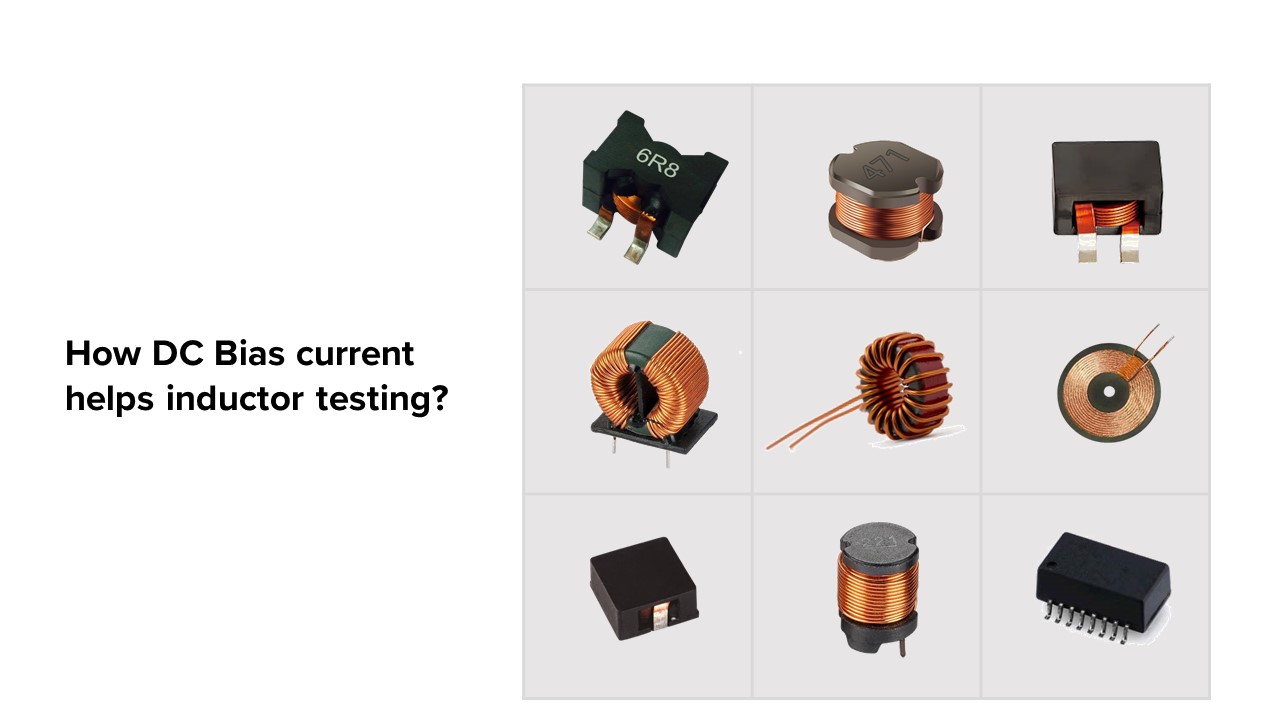
How DC Bias current helps inductor testing?
Ferromagnetic materials (like iron) are composed of microscopic regions called magnetic domains. The stronger the external magnetic field H, the more the domains align, yielding a higher magnetic flux density B. Eventually, The magnetization remains nearly constant, and is said to have saturated. The domain structure at saturation depends on the temperature.
What is magnetic saturation?
In electronic circuits, transformers and inductors with ferromagnetic cores operate nonlinearly when the current through them is large enough to drive their core materials into saturation. This means that their inductance and other properties vary with changes in drive current. In linear circuits this is usually considered an unwanted departure from ideal behavior.
By setting the important parameters of the instrument, the inductor sensor can be measured. These parameters include:
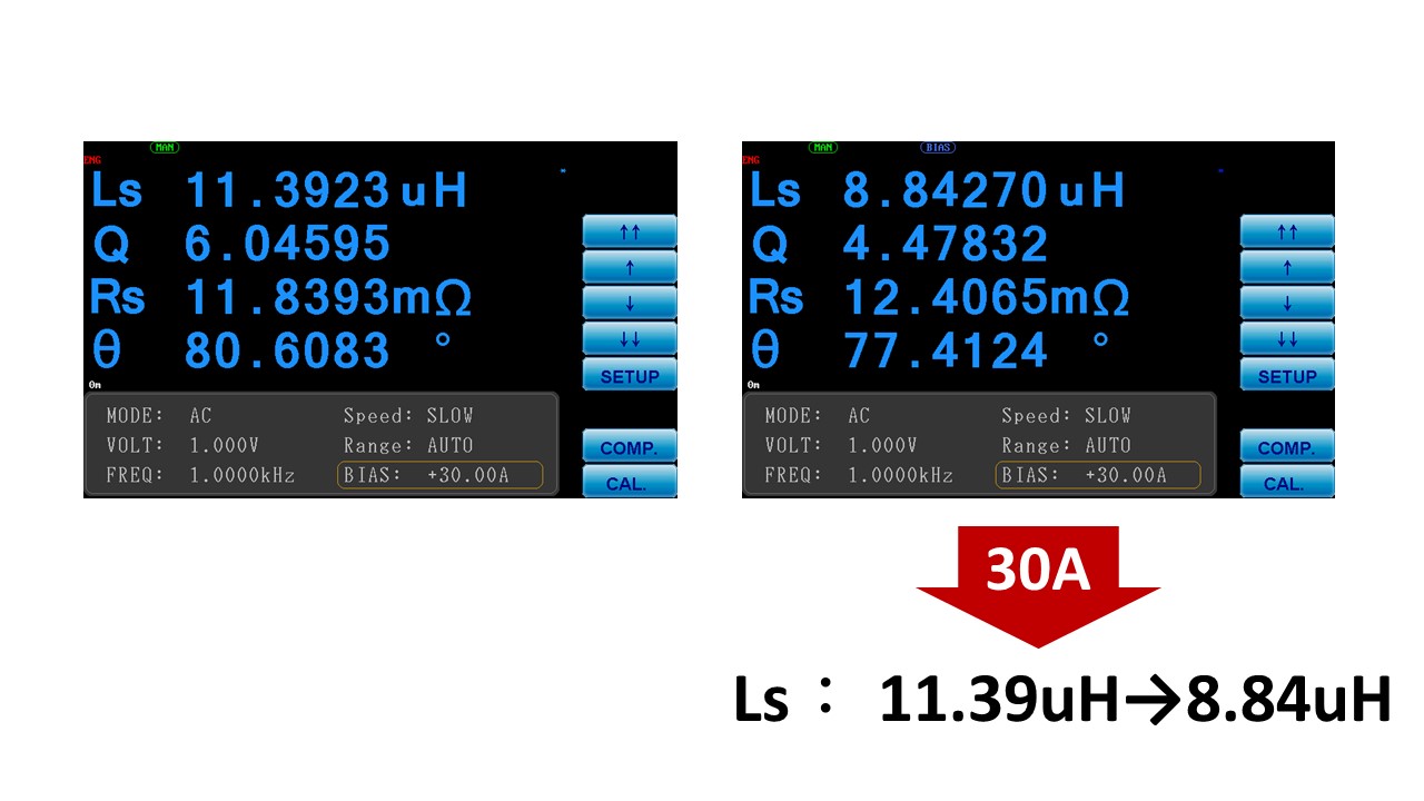
Ls (inductance): Initially measured at 11.39uH and later decreased to 8.84uH.
Q (quality factor): This parameter represents the efficiency of the inductor and is measured under a direct current bias current of 30mA.
By applying a direct current bias during the measurement process, we can more accurately evaluate the performance of the magnetic component under real operating conditions. This approach helps determine the most suitable magnetic core material, reduces the impact of magnetic saturation on component performance, and minimizes the risks of heating and component damage.
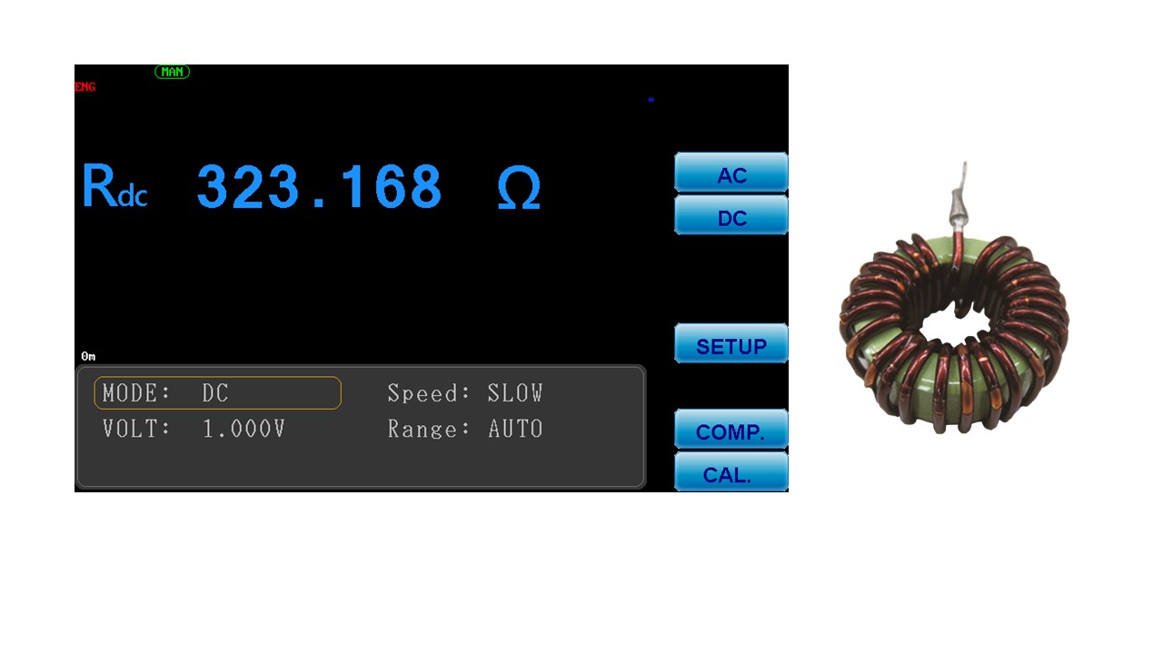
This system supports the functionality of measuring DC resistance (DCR). The DC bias current source testing system can output a maximum of 320A (by selecting either the 6355/6356+6243 models).
One of the important parameters of magnetic components such as inductors is the DC resistance (DCR). This parameter reflects the level of resistance that the inductor exhibits to direct current. The DC resistance of an inductor is primarily determined by the conductor material and coil structure of the inductor component. Measuring the DC resistance provides an assessment of energy consumption, energy loss, circuit efficiency, and power dissipation of the inductor component in a DC circuit. It helps confirm the response of the inductor component to changes in DC current and aids in evaluating the stability of the circuit.


