DCT | Test and Measurement

Welcome to our new site! Feel free to report any issues, contact us at [email protected]

DC Bias Current Test System 6355+6243

DC Bias Current Test System 6355+6243

  • Wide Frequency Range  Supports 100Hz to 200kHz for comprehensive inductor testing.
  • High Current Output  Delivers up to 40A per unit, expandable to 320A with 8 units.
  • Optimized Power Efficiency  Operates with a maximum power consumption of 640W.
  • Scalable & Modular  Configurable system for flexible DC bias current testing.
  • Reliable Performance  Ideal for accurate magnetic component characterization and inductor analysis.
Send Enquiry

Features

  • Frequency Response 100Hz-200k/500kHz
  • Supports maximum output DC bias current of 640A/320A/120A
  • DCR measurement function
  • Can sustain maximum power output for long periods of time
  • Output impedance: 100Ω
  • Open/short circuit calibration function
  • Supports meter measurement mode/multi-step list testing

6355/6356+6243H/6243/6223 provide a frequency response range of 100Hz to 200k/500kHz and a maximum output current of 640A/320A/120A. These systems are used for testing inductors, coils, ferrites, and core saturation currents.

Application

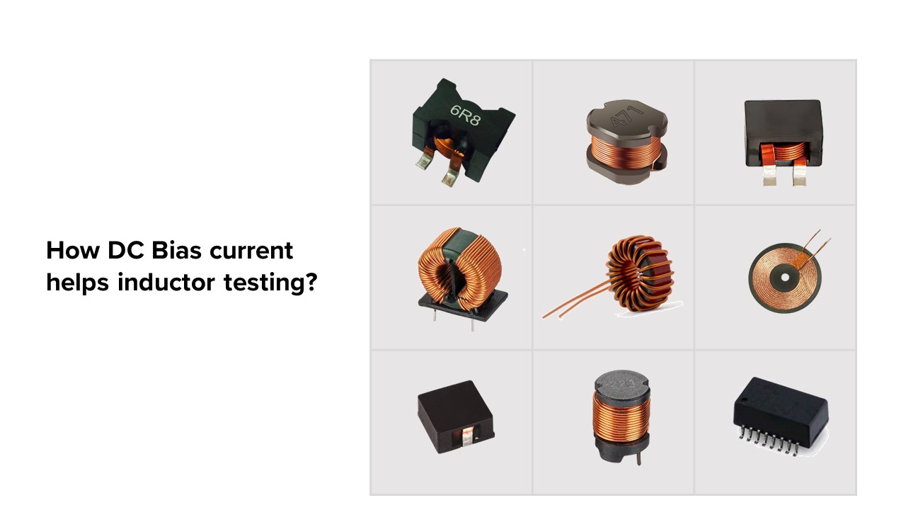
How DC Bias current helps inductor testing?

Ferromagnetic materials (like iron) are composed of microscopic regions called magnetic domains. The stronger the external magnetic field H, the more the domains align, yielding a higher magnetic flux density B. Eventually, The magnetization remains nearly constant, and is said to have saturated. The domain structure at saturation depends on the temperature.

What is magnetic saturation?

In electronic circuits, transformers and inductors with ferromagnetic cores operate nonlinearly when the current through them is large enough to drive their core materials into saturation. This means that their inductance and other properties vary with changes in drive current. In linear circuits this is usually considered an unwanted departure from ideal behavior.


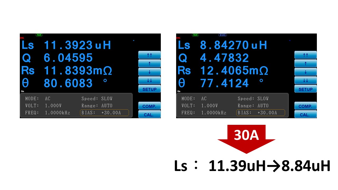
By setting the important parameters of the instrument, the inductor sensor can be measured. These parameters include:

Ls (inductance): Initially measured at 11.39uH and later decreased to 8.84uH.
Q (quality factor): This parameter represents the efficiency of the inductor and is measured under a direct current bias current of 30mA.

By applying a direct current bias during the measurement process, we can more accurately evaluate the performance of the magnetic component under real operating conditions. This approach helps determine the most suitable magnetic core material, reduces the impact of magnetic saturation on component performance, and minimizes the risks of heating and component damage.

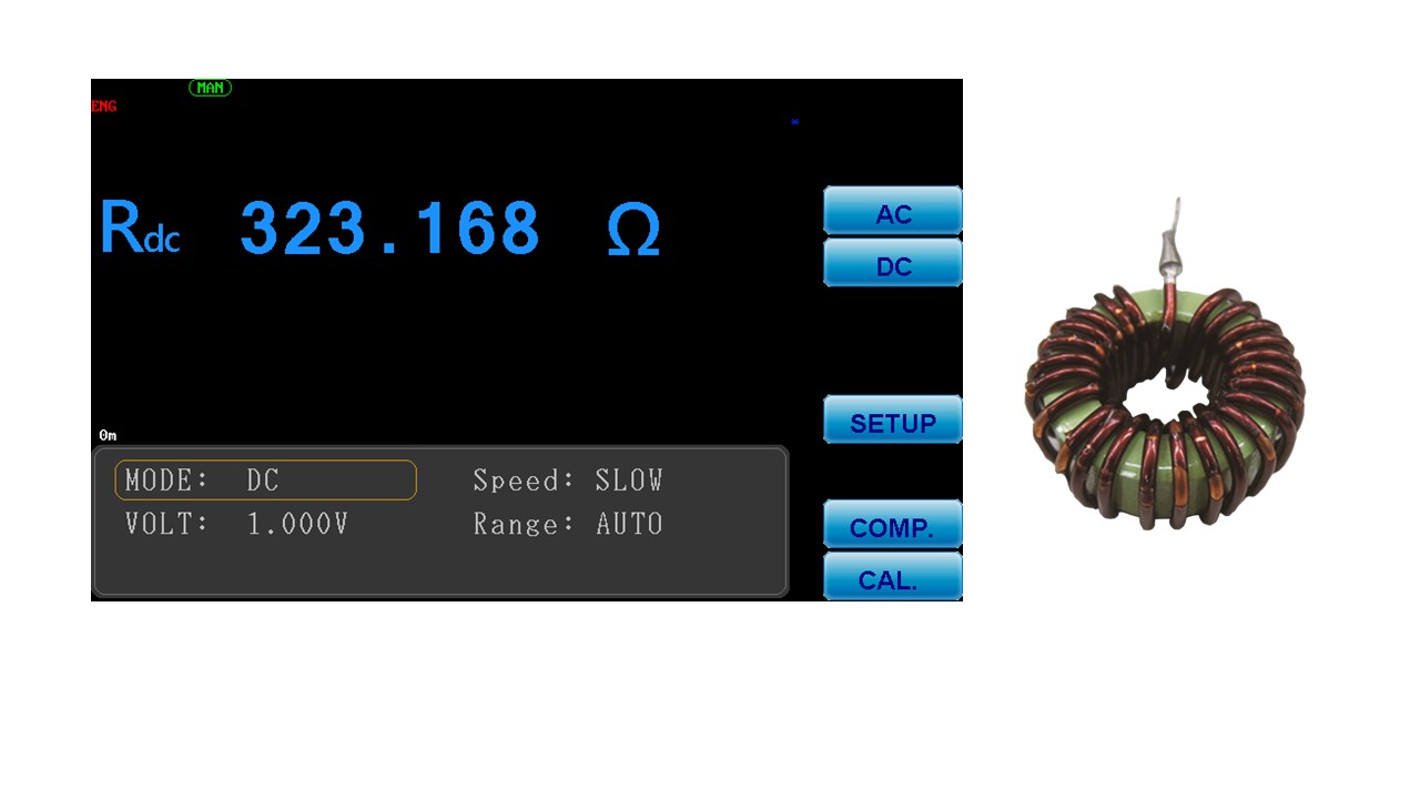
This system supports the functionality of measuring DC resistance (DCR). The DC bias current source testing system can output a maximum of 320A (by selecting either the 6355/6356+6243 models).

One of the important parameters of magnetic components such as inductors is the DC resistance (DCR). This parameter reflects the level of resistance that the inductor exhibits to direct current. The DC resistance of an inductor is primarily determined by the conductor material and coil structure of the inductor component. Measuring the DC resistance provides an assessment of energy consumption, energy loss, circuit efficiency, and power dissipation of the inductor component in a DC circuit. It helps confirm the response of the inductor component to changes in DC current and aids in evaluating the stability of the circuit.


MICROTEST DC Bias Source Test System provides precise verification of magnetic components’ magnetic saturation current (Isat) and temperature rise current (Irms). It is equipped with a DC bias current source integrated with an LCR meter/Impedance Analyzer and can be configured as a desktop unit or integrated into a testing cabinet. Operation settings and test results are displayed on the LCR meter/Impedance Analyzer and can also be accessed through PC connection software.

The DC bias current output ranges up to a maximum of 640A/120A/60A/20A, with frequency responses of 100Hz-30MHz/10MHz/3MHz.

For research and development (R&D) or scientific research institutions, there is the option of the 6632+ / 6632S+ series, which includes a current curve sweep analysis feature.

For production lines, the 6350+ series is available as an option.

Specifications

Selection
 Model 6355+6243H 6355+6243 6355+6223 6356+6243H 6356+6243 6356+6223
Frequency Response 100Hz-200kHz 100Hz-200kHz 100Hz-200kHz 100Hz-500kHz 100Hz-500kHz 100Hz-500kHz
Output Current Max. 640A 320A 120A 640A 320A 120A
Power consumption 640W  640W  320W 640W 640W 320W
units of the DC Bias 16  8 6 16 8 6
Output Current (unit) 40A  40A 20A 40A 40A 20A

SPEC

Current Accuracy 0.000A-1.000A 1%+5mA
1.001A-5.000A 2%
5.001A-40.000A 3%
DCR Test
Constant power output
Current switch

6355/6356 LCR Meter

Model 6355/6356
Frequency Range 10Hz-200kHz/10Hz-500kHz
Frequency Setting Continuity
Frequency Output Accuracy ±0.01%
Frequency Resolution 5-bit Frequency
Basic Accuracy ±0.05%
Drive Level Test Signal Voltage Level            

             AC:10mV – 2Vrms

DC:10mV – 2V 

Voltage Minimum Resolution 1mV
Output Impedance 100Ω
Measurement Mode Meter mode, list mode
Measurement Parameters |Z|、|Y|、θ、X、R、G、B、L、D、Q、DCR、C
Test Time (Fastest) 8mS

6355/6356 Measurement Parameters

Parameters Range
|Z|, R, X 0.001mΩ~99.999MΩ
|Y|, G, B 0.1nS~99.999S
Cs Cp 0.01pF~9.9999F
Ls Lp 0.1nH~99.999kH
D 0.00001~9.9999
Q 0.1~9999.9
DCR 0.001mΩ~99.999MΩ
Δ% -9999%~999%
θ -180° ~+180°

System

   Measurement Circuit Series/Parallel
Correction Open Circuit/Short Circuit
 List Mode 8 steps
  Bulit-in Storge 128 sets
USB Host Storge LCR setting documents, list mode setting document
  Trigger Test Auto, manual, RS-232, GPIB, Handler
   Power Supply Voltage:88~132Vac or 195~264Vac (Switchable)
Frequency:47-63Hz
  Power consumption 300VA (6223)、600VA (6243H/6243)
  Environment Temperature:10℃-40℃
Humidity:20-90%RH
   Dimension  358x148x343 mm (W*H*D) /6355
337×145×525mm (W*H*D) /6223
435×145×644mm (W*H*D) /6243H/6243
  Weight 3Kg (6355/6356)
15Kg (6223)
20Kg (6243H/6243)
Display Color Screen, 7″ TFT (800*480)|6355
Interface RS-232、Handler

Accessories

Standard Accessories

  Power Cord
  DIP Test Fixture-DC Bias Current  (F6210)

Optional Accessories

  PC Link Software
  SMD Test Fixture-DC Bias Current  (F6220)
  BNC+BNC cable

Enjoy:

Send Enquiry For:

DC Bias Current Test System 6355+6243

Israel's Leading Businesses Choose DCT

Israel's Leading Businesses Choose DCT

DCT’s Skilled Management Team has more than twenty-five years of experience and expertise in the local business environment, coupled with a highly motivated group of employees, positions us as the preferred supplier among the major customers in the industry.

DCT Competitive Edge is the prompt response to our customer needs, the online and on-site direct technical support, professional consulting for the best cost/performance solution, on-time delivery, long-term maintenance, and support.

We can get back to you!

Need a Rugged Device?

Fill in the form!

A variety of tablets are available for all use cases.
- only solutions - No obligations -

Our experts can help you find just about anything.

What Were You Looking For? Let us help.